Replacing The Electrics
The wiring on Erik’s layout was not what was originally planned, implemented solely to facilitate an operating session. Sure, it worked, but it could not be described as robust. It has therefore been completely replaced and Erik assisted with the tasks.
It’s a seldom acknowledged fact that nickel-silver, as used in most manufacturer’s track, has a much greater resistance than copper. It therefore makes sense, even on a small layout, to run a copper circuit for power, referred to as a bus, and tap off of it to each section of track.
We had already taken the precaution of soldering dropper feeds to every individual piece of track, and running these down through the baseboard to the underside. Up until now, those droppers were screwed into chocolate block connectors but it looked like a plate of spaghetti despite only having two wire colours.
Today’s exercise was therefore to set up a power bus on the underside of the board, using 1″ slug tape. I use this for the main bus instead of 5mm self-adhesive copper tape to ensure that there is no discernible voltage drop. Similarly, any bridging links were made out of 21A 16WG car loom wire, more than adequate for the job.
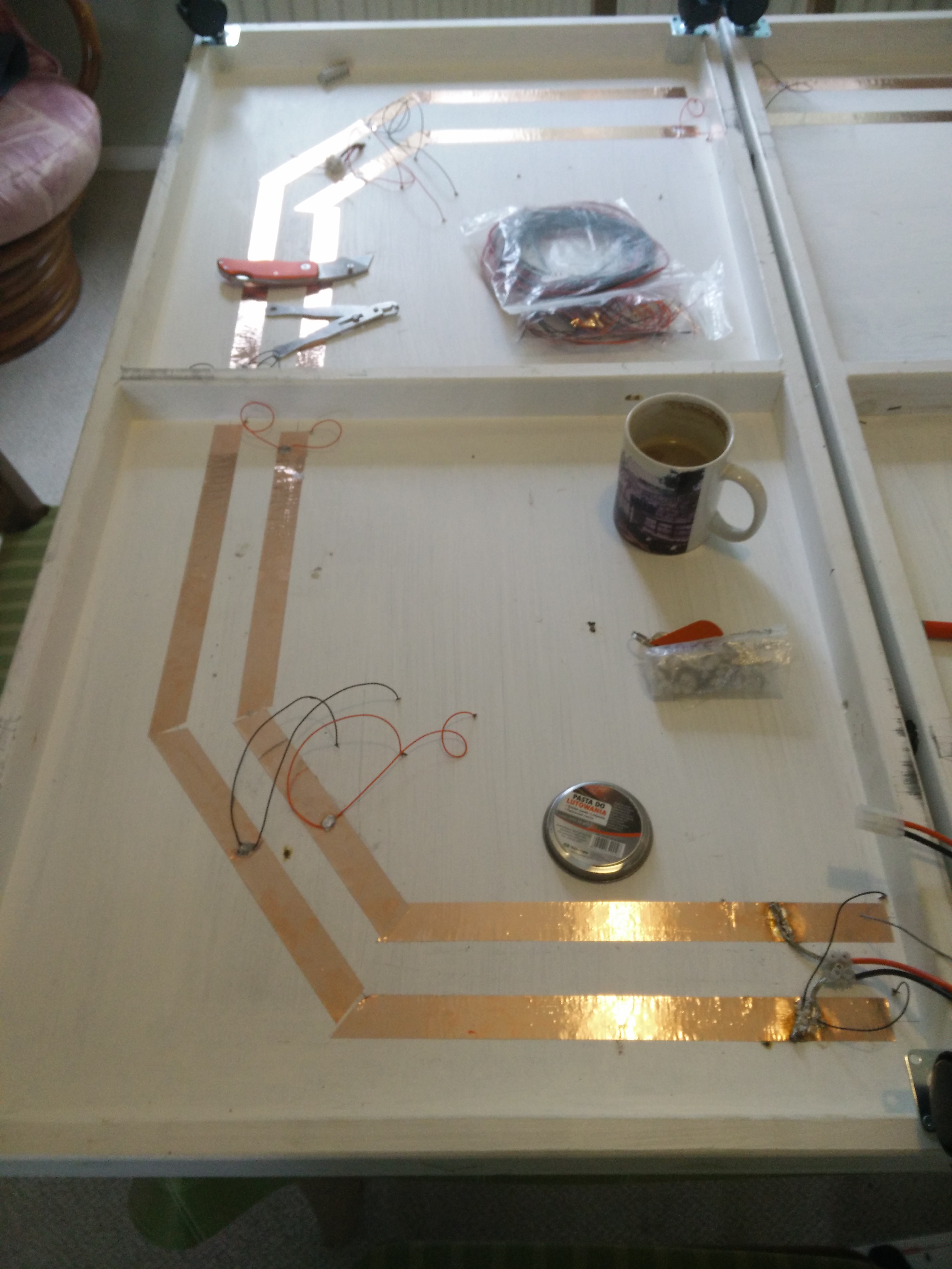 This is the main board, into which the supply and control are fed, through the hole barely visible between the copper tapes in the top-left of this picture. The lengths of copper tape and angles of cut are far from critical, so long as they meet.
The copper tape follows the track on the opposite side of the board, topographically if not faithfully, and you can see the dropper feeds, four of each colour for the four pieces of track in each quarter circle.
The copper tape was burnished into place using a small piece of wood, as much to ensure that it was completely adhered as well as smooth out the wrinkles.
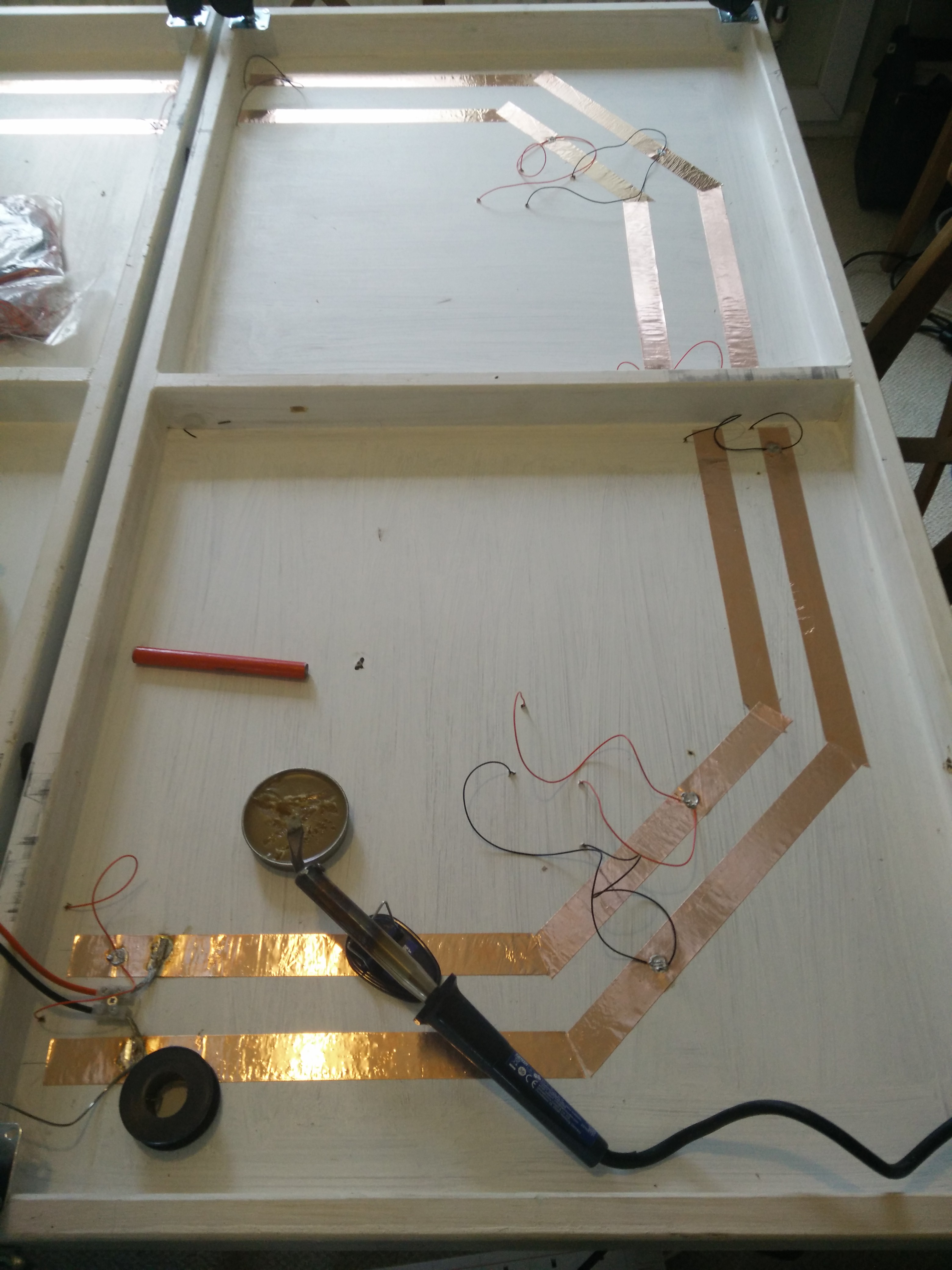 On the second board, you can more clearly see the short lengths of 12V 21A wire, in the same colours, used to bridge the support across the centre of the board.
It might have been easier to simply take the slug tape up and over the support but there is then a risk of it getting torn in transit. This way, all of the connections are protected by the woodwork.
In the bottom-left corner, you can also see the Tamiya connector used to transfer power between boards. The insulation was stripped back so that the wires could pass through a chocolate block as strain relief before the bare wires were soldered to the copper tape. Remember that this railway is for an eight-year old!
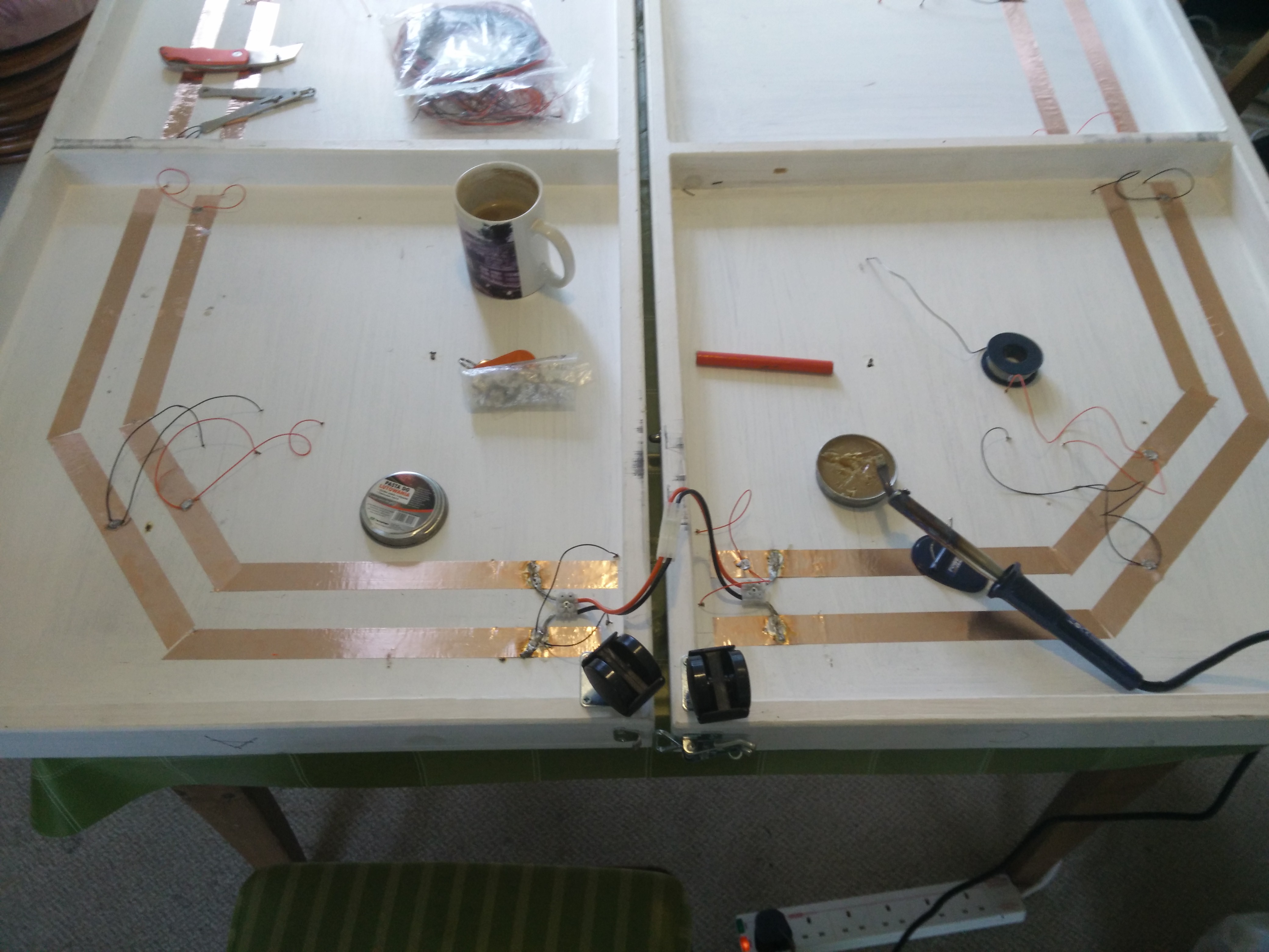 Finally, a quick shot of both boards, the Tamiya connectors in use. These are so easy to use and all but impossible to connect the wrong way round, so ideal for small people.
Just visible in this picture are the solder fillets on the joins in the copper tape, to ensure electrical connectivity.
Are they essential? No idea, because connectivity wasn’t tested until after they’d all been completed.
Testing the circuit showed a resistance of just 7mΩ across every joint and around the whole circuit, so no voltage drop expected here!