Track and wiring
Progress on the modules has been slow, for which read non-existent. With the looming date of the Seaboard Southern show in September, at which these are expected to not only appear but be operational, it’s high time to extract the digit!
A sunny Saturday afternoon with fellow moduler Brian Daly saw:
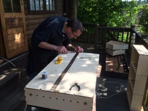 feeder droppers added to two yard lengths of Micro Engineering Code 83 0n30 flexible track
- said track pinned to the boards and soldered to the Gapmaster GM006 units used as end ties
- droppers on the straight boards soldered to the slug tape on the underside
- alignment tested by bolting boards together in various orders and running a skeleton log car
I’ve still got to add droppers to the curved boards and, having had some fun with the alignment, I think I’m going to make a jig for centring the track, just for my own sanity. The fact is that my eyeballs are rubbish at measuring!
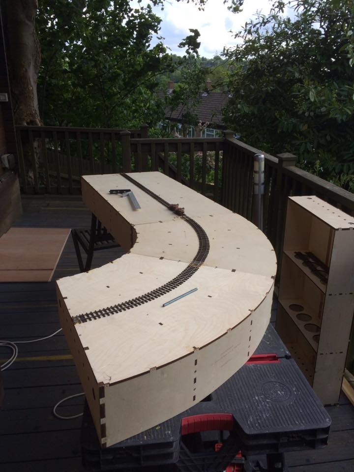 Here you can see the two 45° boards and one straight all bolted up together, with the other straight board standing on its end to the right.
The flowing line of the track can clearly be seen. Module standards discourage connecting the two corners reversed without a straight between them.
Before paint is applied, I think I’m going to put the supplied 3mm plywood fascias on, if only to hide the finger joints and screw holes.
Then it’s time for some scenery!